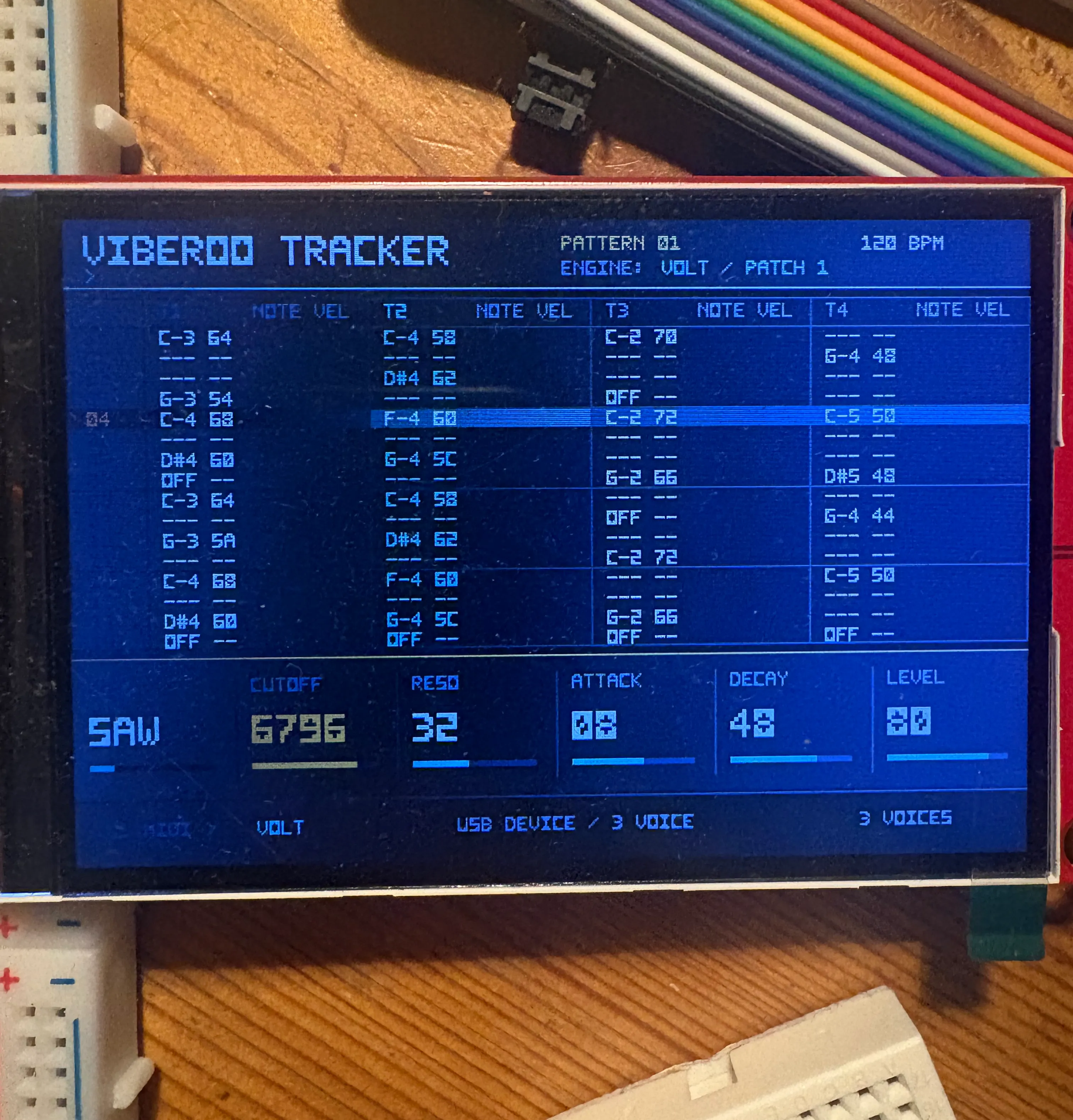
We have wired the LCD and the first set of buttons on breadboards. It is not the neatest version of Viberoo Tracker, but it is an important step toward making the final hardware reliable.
Testing before committing the board
A custom PCB brings all of the instrument's components and connections together in a compact, repeatable form. Once that board is manufactured, however, even a small mistake in a pin assignment or electrical connection can mean another revision and several more weeks of work.
Breadboarding gives us a way to test the design before making that commitment. By connecting the parts with jumper wires, we can verify the circuit one section at a time, compare the physical wiring with the schematic, and correct potential issues while changes are still quick to make.
From interface to physical controls
The screen test confirms that the tracker interface renders correctly on the intended LCD rather than only in the browser prototype. We are also checking that button presses are read consistently and that the control assignments in the firmware match the planned PCB connections.
This setup helps uncover the practical details that are easy to miss on paper: signal behavior, power requirements, startup timing, and interactions between components. Each issue found here is one less surprise in the first assembled PCB.
Next: finalize the schematic
With the display and controls working together, the next step is to fold what we have learned back into the schematic and board layout. We will continue validating the remaining connections before the PCB design is finalized for the first engineering prototypes.